Ipinapakita ang mga post na may etiketa na Wiring. Ipakita ang lahat ng mga post

Lunes, Nobyembre 21, 2016

Get Wiring ho train sets


Wiring ho train sets

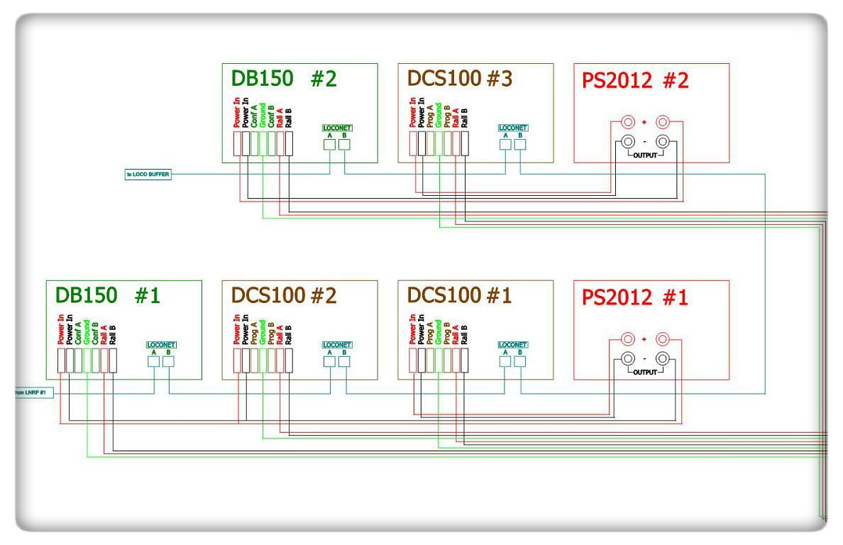
think Image Wiring ho train sets Model Train Layout Wiring additionally Model Railroad Track Wiring

Wiring ho train sets

Ho scale train sets modeltrainstuff.com, Ho scale train sets from popular manufacturers including atlas, athearn and bachmann. we have sets ranging from early steam locomotives to modern diesel and electric. Train sets modeltrainstuff.com, Shop our online selection of train sets from your favorite manufacturers including lionel, mth, bachmann, athearn and many more.. Power/dcc/electrical - train sets only, Power/dcc/electrical if you found yourself on this page and are wondering what the difference is between ac, dc, and dcc, this may help. ..
Fleischmann - continental model railways in ho scale & n scale, Fleischmann are one of the world leaders in model railways. models are produced in both ho gauge (1:87 scale) and n gauge (1:160 scale). for more information on ho.
Layout power and wiring - digitrax, inc., Kb520 general dcc power supply information. there are many transformers and power packs that can supply input power for digitrax boosters & command stations..

Huwebes, Enero 29, 2015

Holiday Wiring Part II


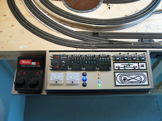
My wiring and control panel are finally complete! The challenge over the last week and since my last post has been to move the control unit down to the basement and to hook it up to my layout.


Model train control panel

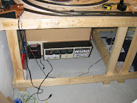
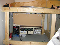
I first attached the back of control unit base to the three 4x4” hinges with six ¼” bolts. This allows the control unit to fold under the table when not in use. However, for the moment I have not yet made a final decision on how the unit will latch when in its upright position, so for now I fastened it up with 3 screws.

Control panel base hingesInstallation of control panel

Installation of control panelInstallation of control panel

I ran the leads from the control unit and hooked them up to the corresponding terminal screws on the previously installed terminal strips. The terminal strips made it very easy to detect any crossed over wires, and even easier to correct the problems as I only needed to swap the crossed wires to the correct screws. Remember, it doesn’t matter how organized or well planned your wiring layout is, mistakes will happen, so leave room to make corrections!

Terminal stripsModel train wiring

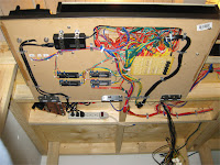
I kept the layout wires attached to the benchwork using small metal cable fasteners. These can be purchased at Canadian Tire for about $1.99 for 20, which compared to other products and retailers I found, is not a bad deal. Small zip-ties also help to keep wires organized and looking neat.

Model train wiringModel train wiring

While testing my control unit, I realized that I needed a higher powered AC power source to power my switch machines, separate from my MRC Tech 4 280 power pack. For this, I mounted an older MRC power pack to the underside of my benchwork, and ran the new AC line back into my control box. This 2nd power source can also act as an additional 12VDC source in the future.

Extra cab controller used for AC accessory power sourceMain power bar and surge protector

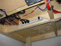
To provide reliable safe power to the different components, I installed a surge protected power bar below my benchwork for all the components to plug into. This is then connected by and extension cord to the wall outlet.

Master power switchMaster power switch

I didn’t plan a master on/off switch into my control panel design, which is something I most definitely should have done, as I have no way to turn my components off (not including the power pack). To solve this, I purchased a rocker switch ($2.99 from Princess Auto), rated at 120V 20A, which I tapped into the cord on the power bar. I then mounted the switch into a standard light switch cover panel that I painted dark brown. I drilled a hole into the front of my benchwork beside my control unit so the rocker switch panel could fit flush against the bench. This switch now cuts the power off to the power bar, so I can leave my layout plugged into the wall outlet at all times.

Master power switch installationMaster power switch installation


Master power switch splice into main power

The track signals are still all displayed together on a temporary paper panel. This is purely for testing and making sure the signals work correctly when switching tracks. They will eventually be positioned on standards in the necessary positions along the tracks.

Finished control unitTemporary trackside signal holder

Other than a few small required adjustments, everything works great as far as the electrical system goes. The dual cab control works awesome, and I couldn’t be happier with how everything turned out. The next step will be to find a method to easily raise and lower the control panel and latch it when it’s upright. I’m also going to start smoothing out flaws in my track work and most importantly, take out the steep grade coming off of my trestle.

Model train control panelModel train control panel

Model train control panel LED

Also check out my Design and Planning page for updated schematics for different systems on my layout so far!

Lunes, Oktubre 6, 2014

Holiday Wiring Part I


The last 2 months have been insanely busy for me, so up until last week, I haven’t had much time to concentrate on my layout. My goal was to complete my wiring and my control panel by new years, and even though it’s the 5th of January now, I’m not that far off of my goal! My work was closed over the holidays and this gave me almost enough time to really concentrate and complete my control panel. I managed to battle the weather last week and made it to Calgary to purchase the last of my supplies for my electrical system. I purchased a MRC Tech 4 280 dual cab controller for my power, as well as 4 Atlas snap-relays to power my x-section, track signals, indicators, etc.


MRC 280 Tech 4 controller
As mentioned before, my control panel and controller need to be able to fold away under my layout when not in use do to the small space. I purchased a 1/2” thick hardboard panel to use as the base to which my control panel and controller will bolt to. The rear of the hardboard panel will attach to hinges located under my bench work, allowing the entire unit to swing under the layout when not in use. I used ‘L’ brackets bolted to the sides of the control box to fasten the control panel to the base. Below you can see where the controllers and control box will sit on the base and where the base will be cut.

Control panel bracketsMRC 280 Tech 4 controller

Once the base was cut, I cut a large opening to allow access to the inside of the control box. I also drilled holes at this time for the controller wires and power cables. A scrap piece of aluminum the same colour as the control panel was used as the base for the cab controller, and glued to the base. I used small black metal eyelets around the drilled holes for the main power leads to make them look more appealing. At the same time, I attached my 4 snap-relays to the bottom of the base.

Controller base with Atlas Snap RelaysController base with control panel

Only the first 8 inches of the base will protrude out past the layout, and the majority of it will be covered by the control box. To cover the visible hardboard, I attached ¾” titanium L molding around the edges, just as I did on the control box itself. As before, I used PL Ultimate construction adhesive to glue the trim.

Controller base with titanium trim and access hole

While the trim dried, I used this time to start wiring everything together. The first item on my wiring list was to connect all the leads from the 8 turnout signals to my resistor board. I also started connecting leads to all of the LED lights and volt meters inside the control box white it was still detached from the base.

Trackside signals connected to resistor boardTrackside signals connected to resistor board

The leads from all of the LEDs were then connected to their appropriate leads on the resistor board and all connections were soldered together and insulated with electrical tape. As I made connections, I tested each circuit to make sure everything worked. One advantage of having all the resistors together on the PC board is that it was very easy to test each resistor anytime I had a short circuit. It was also at this time I decided that the resistor board would be mounted outside of the control box, as it would be to cramped inside.

Turnout position indicator LED wiringResistor board installation on control panel

I then mounted the control panel to the base panel with 4 bolts which were fixed to the 4 ‘L’ brackets fastened to the control box. I mounted the resistor board to the bottom of the base using brass bolts and used brass nuts and foam blocks to support the PC board. At this time I also made a schematic on my computer, showing which resistor is which on my PC board, making it much easier when testing.

Resistor board installed with brass bolts

The cab controller also needed to be attached to the base, however did not have any brackets or holes to do this. With a little research and testing, I discovered that the MRC cab controller is quite hollow, as the printed circuit is located right below the top panel, leaving the bottom entirely open. I started by drilling 2 very small holes through the bottom to inspect to make sure I wouldn’t hit any important electrical components. I then drilled larger holes to accommodate a large threaded screw. I drilled 2 holes through the base; passed the large screws through and screwed each screw about ¼” into the controller. This worked great, and securely attached to cab controller to the base. I ran the power cord through a drilled hole below so it would not be visible on top.


Control panel wiring

I spent about 4 entire days wiring everything together. This included making all the connections, soldering, and insulating. Once each circuit was made, I needed to test each one. Everything worked well with the resistor board for all the LED lights on the system, with only a few shorts that were located and fixed relatively quickly. I spent a lot of time setting up all of the snap-relays as well, making sure that the correct indicator LEDs and switched were activated/lit when the switch control was flipped.

Control panel internal wiringAtlas snap relay wiring

Atlas Short Circuit Note: One of the most frustrating shorts I had to deal with had really nothing to do with my wiring at all! It had to do with the actual Atlas controller, selectors, and switches on the top of my control box. It turned out that the screws supplied to attach each lead to each Atlas device protrudes further then the base, which in turn contacted the aluminum surface of my control box causing a large system-wide short. I resolved this by making a small copper washer for each screw.

Terminal connectors on Atlas selectors

Testing everything as I went along took a lot of extra time, but was worth it in the end as problems could be fixed immediately and could easily be identified, opposed to having everything together in the end and having to sift through everything. Another problem I found was with my switch overload indicator lights. I didn’t take into account that when one AC lead was powered, that the second AC lead would also be powered as both were connected together where they contacted one of the bridge rectifiers AC posts. This was easily resolved by putting diodes into each converging line, preventing current from traveling down the other lead when powered from either side (as seen below).

Diodes for switch machine overload indicatorsPower block electrical leads

I put all of my future track signals in a temporary holder at this time as well so I could easily view them when testing, as seen below. They all worked perfectly fine and matched the switch positions perfectly. A switch on the control panel turns the center amber lights either on or off. I then attached my accessory 12V rectifier to the bottom of the base with handmade brackets. This 12V DC power source powers all of the future accessories and LED lights.

Control panel wiring12 volt laptop inverter

I used small brackets to fasten all the cables to the bottom of the base. There was such a large amount of wiring that it was sometimes difficult to keep everything perfectly organized, or at least as organized as I wanted it. All the main wires that connect to the layout run off the back of the base where it will be hinged, and will connect to their appropriate screw on the layouts terminal strips.

Control panel wiring almost completeControl panel wiring


Completed control panel wiring

Now that the control panel and all the wiring is completed, I plan to have it attached to my layout by the end of this week. Once I complete this, I will post the second part to this update.
Martes, Agosto 5, 2014

Electrical Block Wiring


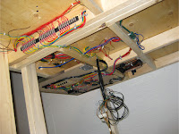
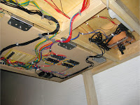
I’m waiting for a few last parts to come in for my control box, so I’ve instead been working on wiring the underside of my bench-work. I purchased 3 - 10 position terminal strips off eBay and attached them to the main support frame. I then connected all of the different power blocks to the corresponding terminal connector. All of the switch machine and turn-table controls were also wired to the terminal strips. The common DC and common AC grounds terminate on the strips as well. The wires from the control box will come through the large hole to the right of the terminal strips, and will attach to their appropriate terminal position screw.
Terminal stripsTerminal connector wiring

I tried to keep the wires as organized as possible; however, since I wired the layout in stages, the final wiring resulted in lots of connection in the individual leads. For these connections, I used high quality male & female connectors, wrapped in electrical tape to prevent loose connections.
Electric block wiring

I have also decided to build my own track signals from scratch. I purchased the small LED lights and black display faces off eBay for a very reasonable price ($5.00 for all of the LEDs and 8 black display faces). I used super glue to attach the LEDs to the display faces. I then soldered all the grounds together, and ran one common ground to all 3 LEDs. I then soldered individual wires to each LED.
Lit scratch built trackside signalScratch built trackside signal

These wires will then go to the control box and their corresponding relay switch, which will control what LED is lit up depending on the turnout position. I used standard telephone cable for my leads, which worked perfectly as there was a black, red, yellow, and green wire which matched perfectly to the LED light colours. I still need to figure out how I’m going to construct the rest of the signal structure, but I’ll save that for the new year!
Scratch built trackside signal