

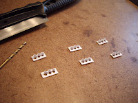
I started by cutting the face plate for each traffic light from thin styrene sheet, then carefully drilled 3 – 2mm holes in each face plate, spacing each hole 1/8” apart (center to center). For the lens shades, I used a single hole punch to punch out round pieces from very thin styrene. I cut the styrene disk back 2mm from its edge, trimmed each pointy edge, and shaped each piece by gently rolling it between my fingers until it had the correct curve to fit over each LED. I was able to make 2 shades from each styrene disk. I then glued 3 of these directly above each hole on the face plate.
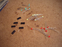
I masked the backside of each face plate, and sprayed the front flat back, figuring that it would probably be easier to paint these prior to installing the lights. I masked the back side to prevent paint from getting on this area, which would need to be removed anyways when it came to gluing the LEDs to the face plate. I then counted out 6 LEDs in each colour (red, yellow, green) and tested each one with a resistor and power supply to ensure each one worked.
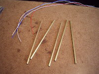
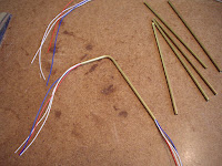
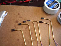
For the light standards, I used 3/32” diameter copper tubing, which I cut into 4” sections. I cut the sections at 4” so I had extra length to insert into the pilot holes in my layout when it comes to installing these. I needed to thread 4 wire leads through each, so the wires needed to be quite thin. I found an old computer hard drive ATA cable, which is comprised of several dozen very thin insulated wires, so I cut this up and saved the wire leads. I then threaded 4 wires through each copper tube, one for the green, yellow, red LEDs, and common ground. There were only 3 colours of wire however (red, blue, and white), so I just used a second white, marking it with a black sharpie for use as the common connection.

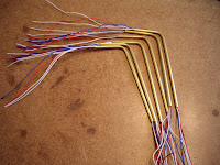
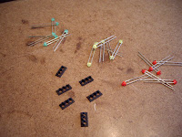
Once the wire leads were threaded through each copper tube, I bent the top of each tube to an almost 90 degree angle about 1” from the one end. I bent the curve over a thick marker container to keep the curve uniform and round. It’s also very important to make sure that the wire leads are pre-installed in the copper tubes, as the tube needs the internal support when bending. Without the wire leads inside, the copper tube would simply collapse and kink.


By this time, the paint on the front of the face plates had dried, and it was time to install the LEDs. I first cut off the long connectors to each LED with flush cutters, leaving only a small portion protruding from the back of each LED. I then glued each LED with CA to the back of the face plates, making sure the anode (+) connection on each LED was on the top position. You can distinguish what side is the anode connection on most LEDs from the curved profile on the base of the LED itself. The cathode (-) side is flat and squared off, and the actual connection lead itself is usually shorter than the anode.
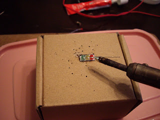
Now for the fun part; soldering the connections to the LEDs. I used a small cardboard box which I cut a notch into for the front of the faceplate to fit into for support. The common (-) connection was the first one that I made. For this, I used one of the metal leads that I had originally cut off of the LEDs, spanning it across and soldering it to all three cathode connections on the LEDs.
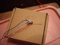

For the controlled (+) connections, I carefully soldered each wire lead from the copper tube supports to the anode on each LED. I soldered the red wire to the red LED, the blank white wire to the yellow, and the blue one to the greed LED for each traffic light. The other white wire, which I previously marked with a black sharpie, was soldered to one end of the common connection. When soldering the wires, I made a point of positioning each wire so it would easily exit off to one side of the traffic light (the side facing the support column). This made the back of each street light look a lot less cluttered and easy to work with.


Once all connections were made, I gently and carefully (and I stress the gentle part), pulled the wire leads at the base of the copper tube supports, slowly bringing each traffic light closer to the support column. After I had positioned each traffic light right up against the copper tube supports, I adjusted each light so it was positioned level to the ground when positioned upright. The wires provided enough rigidity that no glue was required to fasten the lights to the support column. I then painted the back side of each light, including the connections and face plate, with 3-5 coats of black enamel paint, making sure I put on enough coats that no light was visible from the back of the traffic lights when lit.

The final step was to paint the copper support columns an aluminum colour, for which I used Humbrol metallic aluminum enamel. With the traffic lights now complete, they only now need to be installed and connected to a traffic light controller on my layout. I am currently exploring a couple of options for controllers, including building my own. That will all however be in my Traffic Lights – Part II post, which will hopefully be up sometime this summer. For now, I will return back to my current task of building more trees.


0 (mga) komento:
Mag-post ng isang Komento