A note about this post: I do not take any credit for the design of this circuit, not even for my own rendering and modifications of the circuit schematic. I instead turn the spotlight on Rob Paisley and his website, who has without a doubt spent an unimaginable amount of time, effort, and talent developing dozens of model railroad circuits that ultimately make our layouts achieve things we never thought possible. The intent of this post is to only describe my experience of applying and constructing Rob’s designs on my own layout. Please visit Rob’s website (HERE) , which has a wealth of wiring information and useful model railroad circuitry.
-Tyler
If there is one thing that I learned from building my layout thus far, it’s that the most time consuming, frustrating, problematic, and complex projects usually are the ones that are taken for granted, often fading into the background or going unnoticed when combined with all other aspects of the model. And my traffic lights were definitely no exception to this. Now, I’m not exactly saying my traffic lights go unnoticed, (they are definitely a nice feature) but I myself somewhat took for granted the electrical complexity behind making all the lights synchronized, especially because I was building the entire system, from lights to controller, completely by hand. I know commercial controllers are available from $40.00 to $100.00 (or higher), but doing it myself just seemed more appealing.
Last year while searching for methods to synchronize model traffic lights, I came across Rob Paisley’s 20 output sequencing circuit (HERE). Rob had designed a circuit that essentially created 20 separate outputs that progressed one at a time from 1-20 in a continuous loop. When combined with a novel lighting circuit, synchronization of an entire intersection in both directions is accomplished within the 20 output steps, then repeats. I am going to refrain myself from even trying to go into detail on the particulars of this circuit, as Rob Paisley has already explained it in depthon his website. Rob’s site includes detailed diagrams and parts lists, as well as in-depth explanations of how the circuits work. Rob also offers commercially built circuit boards and kits for this and other circuits he’s designed on his website, but nonetheless, I was determined to build it myself.
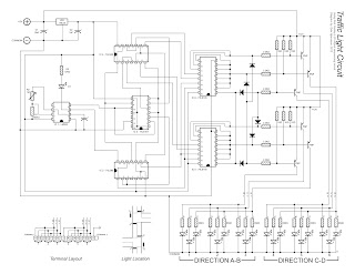
After placing my parts order with Mouser Electronics (using the parts list off of Rob’s website), I went to work putting together my own wiring schematic for this circuit, as shown above. I made my own schematic for 3 reasons. First was because I wanted a plan of the entire circuit, from the controller right to the lights on the layout. The second reason was to plan the actual layout of the circuit board. I drew the schematic in a way that I could literally plan exactly where every connection and lead would go when building the actual circuit, ensuring that everything was spaced correctly so I didn’t run out of room on my PC board. The third and final reason was to better understand how the circuit itself worked. Even though Rob explains the function and how this circuit works in detail on his website, if you do not have a good understanding of it yourself, then it will be a lot more difficult to construct and even harder to troubleshoot. I am no electronics expert myself, so I spent a lot of time researching each component and IC, finding and reading the datasheet for each one as Rob recommends on his website.

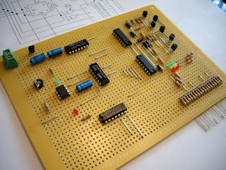
Once all of my components arrived from Mouser, I purchased a 2200-hole PC board from The Source, and eagerly went to work putting it together. I used my schematic almost exclusively to construct the circuit on the PC board, marking off each completed component and section of the circuit with a highlighter to ensure I didn’t get lost or miss a connection, or worse, make a wrong connection. Double, triple, and quadruple checking my work against my schematic as well as Rob’s original wiring schematic almost guaranteed no major errors were made.

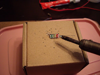
I used my soldering iron to make all the connections on the back of the PC board, and used bare steel wire for the leads between connections. Special consideration needs to be made for spacing of connections that pass over each other, which requires the steel lead to pass up through the PC board, over the existing connections below, and then back down through the PC board to its intended location. Care must also be taken when soldering connections that are right beside each other, as it is easy to unintentionally solder two separate connections together. There were also several spots on the PC board where the soldered connections were shorting out on each other because they were so close to each other, so I carefully used a razor blade to “scrape” the space in between each connection, ensuring the connections were no longer touching.

You will probably notice when comparing my schematic to Rob’s schematics that the LED traffic light portion of my circuit utilizes PNP transistors to control the LED lights, whereas Rob’s examples show the LEDs connected directly to the 20 outputs. The reason for this is because the 20 outputs of the circuit are LOW (negative). To control the red, yellow, and green LEDs of the traffic lights, the LEDs need to be supplied with a common positive (+) current, connected to the anode of each LED, and a separate negative (-) ‘controller’ lead connected to the cathode of each LED, and then to each output of the controller. However, I built my traffic lights the opposite way, with a common negative and separate positive controlling wires. Thus, my lights could only be controlled by applying separate POSITVE current connections to each LED, where the 20 output circuit controls the LEDs by separate NEGATIVE current connections to each LED.

To get around this issue, I applied Rob’s wiring schematic where he explains how to use the 20 output circuit to control high-current bulbs by utilizing PNP transistors as switches. In other words, instead of directly controlling the LED lights by having them directly connected to the 20 outputs of the controller, I used the 20 outputs to control the PNP transistors, which act like switches, either allowing or stopping the separate positive, high current (12v) flowing through to the bulbs. The transistor’s switching capability is controlled by its base terminal, which is connected to the 20 outputs of the controller. I then simply replaced the high current bulbs with resistors and my LED traffic lights.
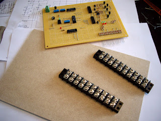
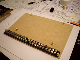
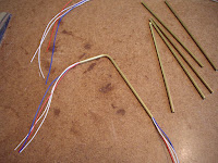
Once the circuit was completed, I needed to make the connections from the controller to 2 – 10 position terminal strips, which I would then later connect each traffic light to. To do this, I first cut a piece of tempered hardboard, to which I attached the 2 terminal strips along the bottom edge. I used ¾” brass flat-head machine bots applied from the back of the hardboard to fasten the terminal strips, allowing the hardboard base to lay flat. I also installed an additional 4 bolts through the hardboard base to support the circuit board, allowing it to be secured without having its bottom circuitry come in contact with the hardboard base.

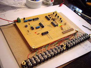
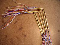
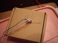
The final step was to connect each positive output on the circuit board to the screws on the terminal strips. I used high-quality phone cable to do this, which is convenient because most telephone cable contains a red, green, yellow, and black wire, making it easy to colour-code each terminal based on what colour LED will be connected to it. I have a total of 6 traffic lights on my layout, so a total of 18 separate LEDs, 6 of each colour, and one common negative, so a total of 19 connections. The first 9 connections will control 3 complete traffic lights in a north-south direction, and the following 9 will control the other 3 complete traffic lights in an east-west direction.
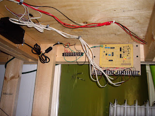
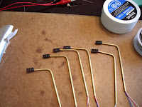
After I had attached everything to the hardboard base, I installed the entire module unit under my layout. The circuit requires a 12 volt DC power source, so I connected it to a 12 volt terminal on a previously installed power terminal strip. I had already installed my actual traffic lights on my layout’s intersections, running the wires to the underside of my layout through 1/8” pilot holes. I utilized telephone cord again here to connect the traffic lights to the terminals on the controller module. After connecting each traffic light to its corresponding power terminal on the control module, all that was left was to test it. And just like that, I now had working traffic lights on my layout!

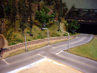
Well, it wasn’t really “just like that.” I spent days and countless hours pulling my hair out for over a week, testing and trying to locate small short circuits that arose over and over again on both the control module and in the traffic light wiring itself. With so many small connections so close to one another, it’s pretty much impossible to get it right 100% the first time. There were nights were I literally had to walk away from the entire project in frustration, but after sleeping it off, I always tackled it the next day with a fresh and positive attitude. In the end, the final result was a working, fully automated, synchronized traffic light system, which I will definitely never take for granted. And to be honest, if others don’t notice it, it’s only because it’s working how it should.
Check out my YouTube video showing my hand-built traffic lights and controller based on Rob Paisley’s 20 Output Sequencing Circuit in action!